
SI Serisi ISO15552 Silindir
Ürünler
Features
1. The cylinder is in accordance with the ISO15552.
2. The piston seal adopts two NBR+PA material as Y type one-way sealing structure with compensation function, long service life and low starting pressure.
3. The rod seal uses PU material with the characteristics of high strength, good toughness, wear resistance,oil resistance and aging resistance.
4. The piston rod material is made by 45C Carbon Steel with hard chrome plating on the surface, and the roughness Ra<0.4, with good wear
resistance and rust resistance.
![]()
Internal Structure
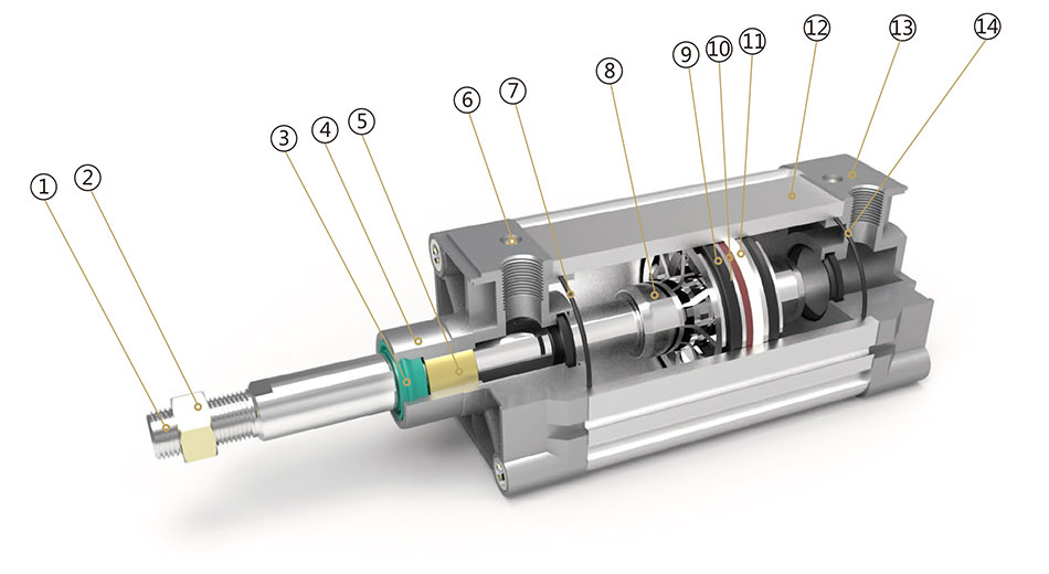
Parts
Number | Name | Number | Name |
1 | Piston rod | 8 | Piston |
2 | Hexagon nut | 9 | Yring |
3 | Shaft seal | 10 | Magnet |
4 | Front cover | 11 | Anti-friction ring |
5 | Copper tube | 12 | Barrel |
6 | Cushion adjust screw | 13 | Back cover |
7 | Cushion seal | 14 | 0 ring |
![]()
Ordering Code
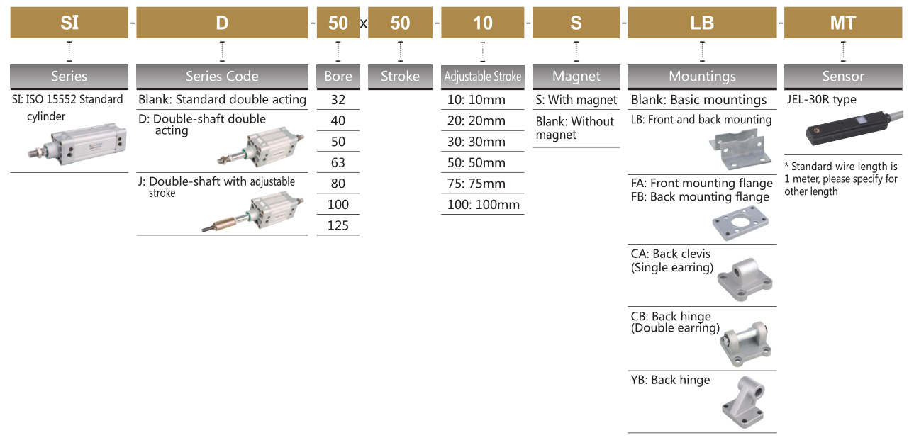
![]()
Specification
Bore (mm) | 32 | 40 | 50 | 63 | 80 | 100 | 125 |
Operation | Double Acting | ||||||
Working Medium | Air | ||||||
Mountings | Basic FA FB CA CB LB YB | ||||||
Operating Pressure Range | 1~9.0 Kgf/cm² | ||||||
Proof Pressure | 13.5 Kgf/cm² | ||||||
Operating Temperature Range | -20~80℃ | ||||||
Operating Speed Range | 50~800mm/s | ||||||
Cushion | Adjustable Cushion | ||||||
Adjustable Cushion Stroke | 20 mm | 26 mm | |||||
Port Size | G1/8″ | G1/4″ | G3/8″ | G1/2″ | |||
![]()
Stroke
Bore | Standard Stroke | Max. Stroke | Allowable Stroke |
32 | 25 50 75 80 100 125 150 160 175 200 250 300 350 400 450 500 | 1000 | 2000 |
40 | 25 50 75 80 100 125 150 160 175 200 250 300 350 400 450 500 600 700 800 | 1200 | 2000 |
50 | 25 50 75 80 100 125 150 160 175 200 250 300 350 400 450 500 600 700 800 900 1000 | 1200 | 2000 |
63 | 25 50 75 80 100 125 150 160 175 200 250 300 350 400 450 500 600 700 800 900 1000 | 1500 | 2000 |
80 | 25 50 75 80 100 125 150 160 175 200 250 300 350 400 450 500 600 700 800 900 1000 | 1500 | 2000 |
100 | 25 50 75 80 100 125 150 160 175 200 250 300 350 400 450 500 600 700 800 900 1000 | 1500 | 2000 |
125 | 25 50 75 80 100 125 150 160 175 200 250 300 350 400 450 500 600 700 800 900 1000 | 1500 | 2000 |
Overall Dimension
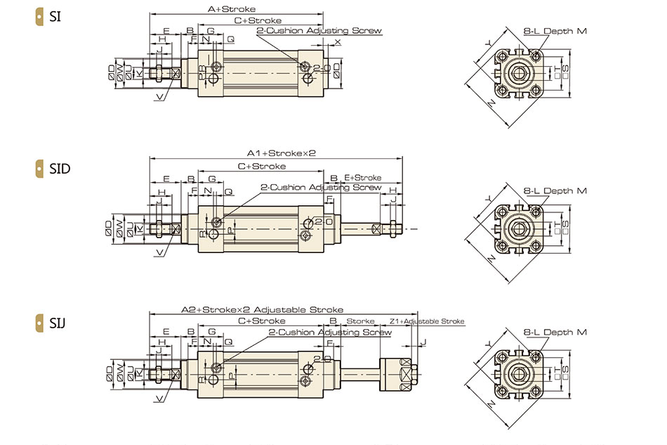
Dimension
Bore/ Symbol | A | A1 | A2 | B | C | D | E | F | G | H | I | J | K | L |
32 | 142 | 190 | 185 | 16 | 94 | 30 | 33 | 10 | 25 | 22 | 17 | 6 | M10x1.25 | M6 |
40 | 159 | 213 | 207 | 20 | 105 | 35 | 34 | 10 | 29 5 | 24 | 17 | 7 | M12x125 | M6 |
50 | 175 | 244 | 233 | 27 | 106 | 40 | 42 5 | 10 | 32 | 32 | 23 | 8 | M16x1.5 | M8 |
63 | 190 | 258 | 247 | 26 | 122 | 45 | 42 | 10 | 36 | 32 | 23 | 8 | M16x1.5 | M8 |
80 | 214 | 301 | 288 | 35 | 126 | 45 | 53 | 10 | 37 | 40 | 26 | 10 | M20x1.5 | M10 |
100 | 229 | 321 | 308 | 40 | 137 | 55 | 52 | 10 | 39 | 40 | 26 | 10 | M20x1.5 | M10 |
125 | 277 | 394 | 378 | 47 | 160 | 60 | 71 | 10 | 43 | 54 | 40 | 10 | M27x2 | M12 |
Bore/ Symbol | M | N | O | P | Q | R | S | T | U | V | W | X | Y | Z | Z1 |
32 | 12 | 15 | G1/8 | 5 | 3 | 65 | 45 | 32 5 | 12 | 10 | 28 | 4 | 46 | 58 7 | 21 |
40 | 12 | 17 5 | G1/4 | 7 | 3 | 7 | 52 | 38 | 16 | 13 | 33 | 4 | 53 7 | 68 | 21 |
50 | 12 | 20 | G1/4 | 7 | 3 | 9 | 65 | 46.5 | 20 | 17 | 38 | 4 | 65.8 | 84.5 | 23 |
63 | 12 | 22 | G3/8 | 8 | 5 | 9 | 76 | 56.5 | 20 | 17 | 38 | 4 | 79.9 | 99.6 | 23 |
80 | 15 | 23 | G3/8 | 10 | 5 | 12 | 94 | 72 | 25 | 22 | 43.5 | 4 | 101.8 | 123.8 | 29 |
100 | 15 | 26 | G1/2 | 10 | 5 | 14 | 112 | 89 | 25 | 22 | 47 | 4 | 125 9 | 148 9 | 29 |
125 | 20 | 29 | G1/2 | 10 | 5 | 14 | 134 | 110 | 32 | 27 | 53 | 6 | 156.9 | 179.6 | 40.5 |
SI Series Standard Cylinder Accessory(Conforms to ISO15552 Standard)
Overall Dimension
LB Foot
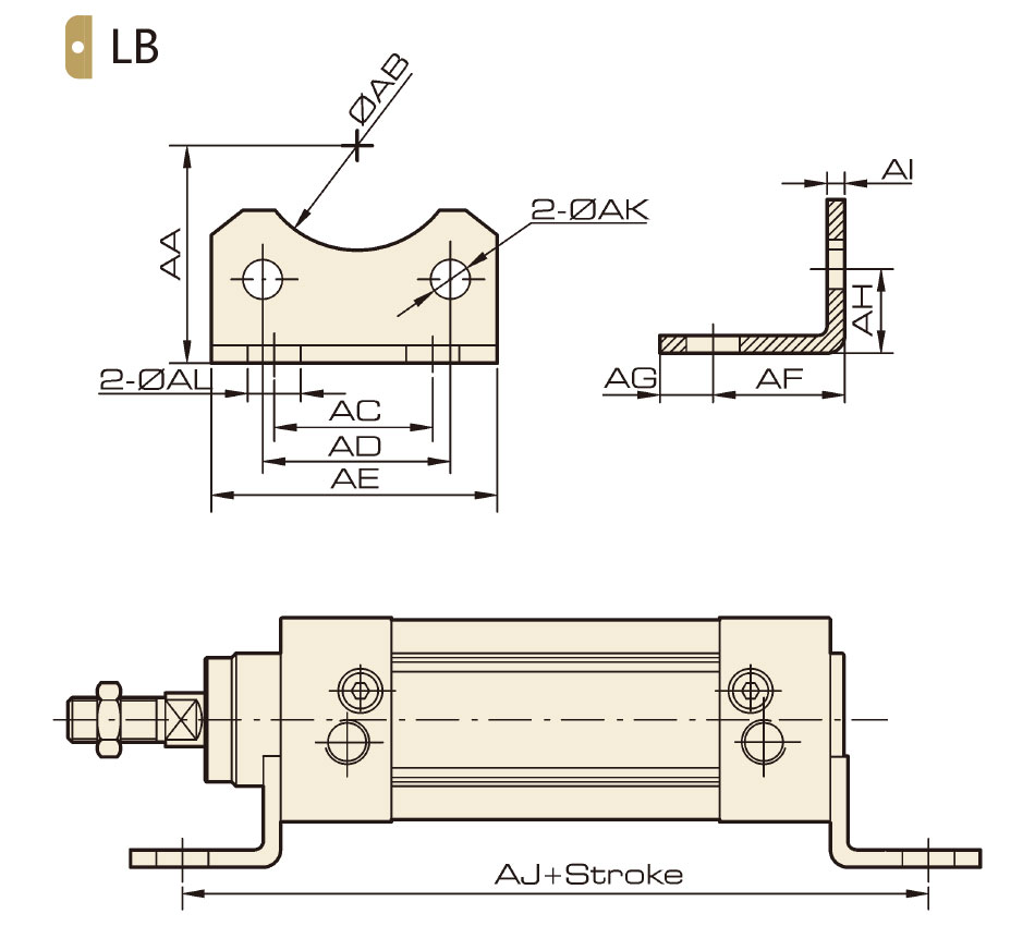
Dimension
Bore/Symbol | 32 | 40 | 50 | 63 | 80 | 100 | 125 |
AA | 32 | 36 | 45 | 50 | 63 | 71 | 90 |
AB | 30 | 35 | 40 | 45 | 45 | 55 | 60 |
AC | 32 | 36 | 45 | 50 | 63 | 75 | 90 |
AD | 32.5 | 38 | 46.5 | 56.5 | 72 | 89 | 110 |
AE | 45 | 52 | 65 | 75 | 95 | 115 | 140 |
AF | 24 | 28 | 32 | 32 | 41 | 41 | 45 |
AG | 11 | 8 | 15 | 13 | 14 | 16 | 18 |
AH | 15.8 | 17 | 21.8 | 21.8 | 27 | 26.5 | 35 |
AI | 4 | 4 | 5 | 5 | 6 | 6 | 8 |
AJ | 142 | 161 | 170 | 186 | 208 | 219 | 250 |
AK | 7 | 7 | 9 | 9 | 11 | 11 | 12.5 |
AL | 7 | 10 | 10 | 10 | 12 | 14.5 | 16.5 |
Overall Dimension
FA / FB Flange
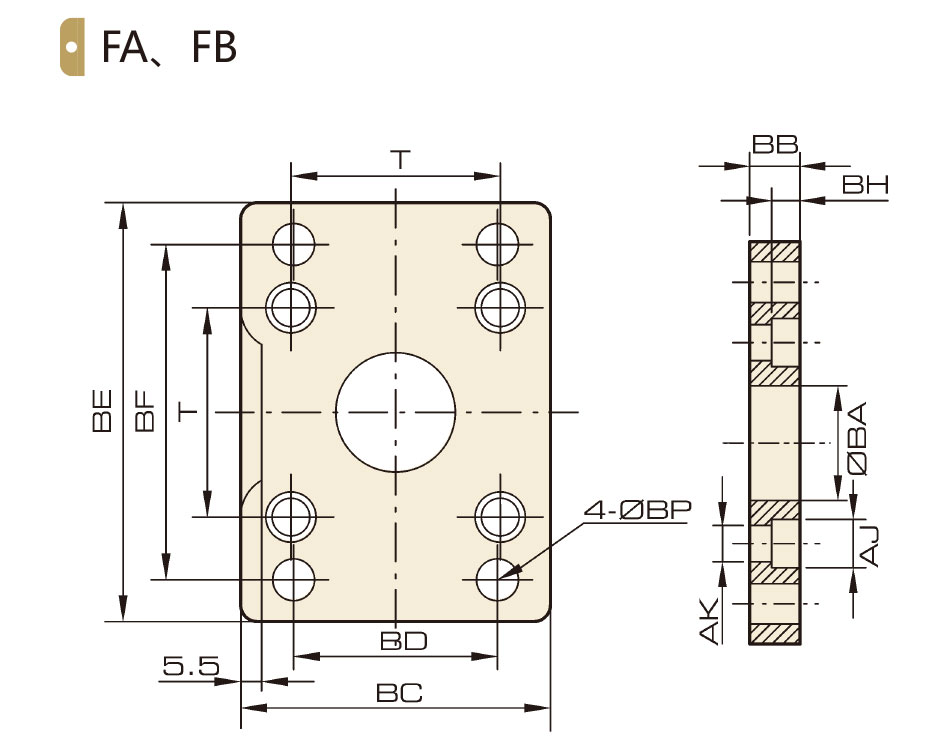
Dimension
Bore/Symbol | 32 | 40 | 50 | 63 | 80 | 100 | 125 |
BA | 30.3 | 35.3 | 40.3 | 45.3 | 45.3 | 55 3 | 60.3 |
BB | 10 | 10 | 12 | 12 | 16 | 16 | 20 |
BC | 45 | 52 | 65 | 76 | 94 | 112 | 140 |
BD | 32 | 36 | 45 | 50 | 63 | 75 | 90 |
BE | 80 | 90 | 110 | 120 | 150 | 175 | 224 |
BF | 64 | 72 | 90 | 100 | 126 | 150 | 180 |
BH | 6.5 | 6.5 | 8.5 | 8.5 | 10 5 | 10 5 | 15 |
AJ | 10.5 | 10.5 | 13.5 | 13.5 | 16.5 | 16.5 | 19 |
AK | 6.5 | 6.5 | 8.5 | 8.5 | 10.5 | 10.5 | 12.5 |
BP | 7 | 9 | 9 | 9 | 12 | 14 | 16 |
T | 32.5 | 38 | 46.5 | 56.5 | 72 | 89 | 110 |
Overall Dimension
CA Hinge
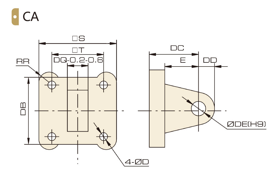
Dimension
Bore/Symbol | 32 | 40 | 50 | 63 | 80 | 100 | 125 |
S | 45 | 52 | 65 | 76 | 94 | 112 | 140 |
T | 32.5 | 38 | 46.5 | 56.5 | 72 | 89 | 110 |
RR | 6.5 | 6.5 | 9 | 9.5 | 11 | 11.5 | 12 |
DB | 34 | 41 | 54 | 65 | 83 | 101 | 123 |
DC | 22 | 25 | 27 | 32 | 36 | 41 | 50 |
DD | 10 | 11 | 13 | 16 | 16 | 20 | 25 |
DE | 10 | 12 | 12 | 16 | 16 | 20 | 25 |
DQ | 26 | 28 | 32 | 40 | 50 | 60 | 70 |
D | 6.5 | 6.5 | 8.5 | 8.5 | 10 5 | 10 5 | 12.5 |
E | 14 | 17 | 17 | 22 | 24 | 25 | 30 |
Overall Dimension
CB Hinge
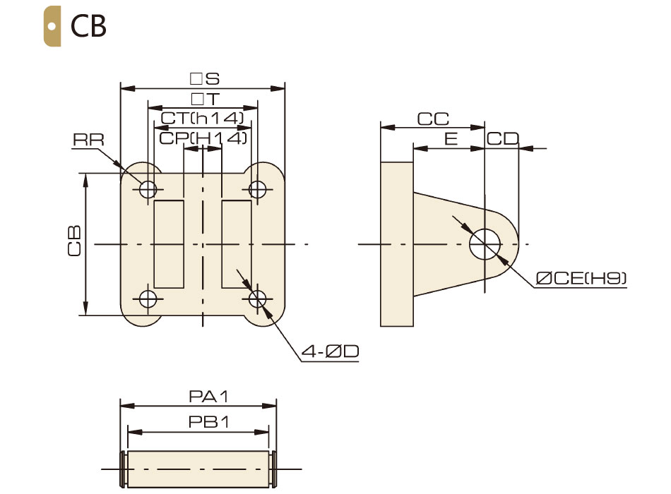
Dimension
Bore/Symbol | 32 | 40 | 50 | 63 | 80 | 100 | 125 |
S | 45 | 52 | 65 | 76 | 94 | 112 | 140 |
T | 32.5 | 38 | 46.5 | 56.5 | 72 | 89 | 110 |
D | 6.5 | 6.5 | 8.5 | 8.5 | 10.5 | 10.5 | 12.5 |
E | 14 | 17 | 17 | 22 | 24 | 25 | 30 |
RR | 6.5 | 6.5 | 9 | 9.5 | 11 | 11.5 | 12 |
CB | 34 | 41 | 54 | 65 | 83 | 101 | 123 |
CC | 22 | 25 | 27 | 32 | 36 | 41 | 50 |
CD | 10 | 11 | 13 | 16 | 46 | 20 | 25 |
CE | 10 | 12 | 12 | 16 | 16 | 20 | 25 |
CP | 26 | 28 | 32 | 40 | 50 | 60 | 70 |
CT | 45 | 52 | 60 | 70 | 90 | 110 | 120 |
PA1 | 53 | 60 | 68 | 78 | 100 | 120 | 130 |
PB1 | 46.5 | 53.5 | 61.5 | 71.5 | 91.5 | 111.5 | 121.5 |
Overall Dimension
YB Hing
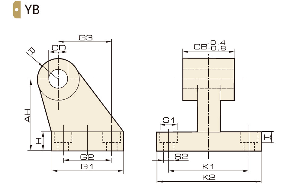
Dimension
Bore/Symbol | 32 | 40 | 50 | 63 | 80 | 100 | 125 |
AH | 32 | 36 | 45 | 50 | 63 | 71 | 90 |
H | 8 | 10 | 12 | 12 | 14 | 15 | 20 |
CD | 10 | 12 | 12 | 16 | 16 | 20 | 25 |
G1 | 31 | 35 | 45 | 50 | 60 | 70 | 90 |
G2 | 18 | 22 | 30 | 35 | 40 | 50 | 60 |
G3 | 21 | 24 | 33 | 37 | 47 | 55 | 70 |
CB | 26 | 28 | 32 | 40 | 50 | 60 | 70 |
K1 | 38 | 41 | 50 | 52 | 66 | 76 | 94 |
K2 | 51 | 54 | 65 | 67 | 86 | 96 | 124 |
SI | 11 | 11 | 14 | 14 | 17 | 17 | 20 |
S2 | 6.6 | 6.6 | 9 | 9 | 11 | 11 | 14 |
T | 1.6 | 1.6 | 1.6 | 1.6 | 2.5 | 2.5 | 3.2 |
R | 10 | 11 | 13 | 15 | 15 | 19 | 22.5 |


